


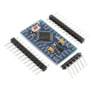
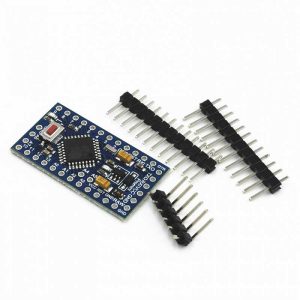
برد آردوینو Attiny85 مدل Micro USB
برد آردوینو Attiny85 مدل Micro USB یک برد از مجموعه بردهای آردوینو است که بر اساس میکروکنترلر Attiny85 طراحی شده است. این میکروکنترلر 8 بیتی از شرکت Atmel دارای 8 کیلوبایت حافظه فلش (Flash Memory)، 512 بایت حافظه SRAM و 512 بایت حافظه EEPROM است. فرکانس کاری آن 16.5 MHz است.
برد آردوینو Attiny85 مدل Micro USB برای ارتباط USB یک کانکتور از نوع Micro USB دارد. این برد شبیه به برد آردوینو Attiny85 مدل PCB USB است، با این تفاوت که این برد کانکتور USB دارد ولی مدل PCB USB بدون کانکتور USB، به پورت USB کامپیوتر وصل میشود.
این برد قابلیت اتصال مستقیم به کامپیوتر برای برنامهریزی (پروگرام کردن) را ندارد. برای پروگرام کردن آن نیاز به سخت افزار خارجی (مبدل USB به سریال TTL یا کابل USB به سریال TTL) است.
این برد 6 پایه ورودی/خروجی دیجیتال دارد. 3 پایه میتواند به عنوان پایه PWM خروجی استفاده شود. 4 پایه از این پایهها هم میتوانند به عنوان پایه آنالوگ استفاده شوند. توجه داشته باشید که این پایهها چند کاربرده (Multi-Function) هستند و در هر لحظه میتوان از یک کاربرد پایه استفاده کرد.
تغذیه این برد میتواند از طریق پورت USB تامین شود یا یک تغذیه خارجی به پایه VIN وصل شود. محدوده توصیه شده برای این تغذیه خارجی بین 7 تا 12 ولت است.
یک رگولاتور ولتاژ با ولتاژ خروجی 5 ولت روی برد قرار داد که پایه VIN به ورودی این رگولاتور وصل شده است.
دو نمایشگر LED یکی برای تغذیه و دیگری برای نمایش وضعیت روی برد در نظر گرفته شدهاند.
تغذیه برد آردوینو Attiny85 مدل Micro USB
تغذیه از طریق اتصال به پورت USB کامپیوتر
تغذیه خارجی. اعمال ولتاژ خارجی به پایه VIN. محدوده تغذیه بین 7 ولت تا 12 ولت را میتوان به این پایه وصل کرد.
هشدار! تغذیه تنها باید به پایه VIN وصل شود. پایه 5V در JP2 تغذیه خروجی است. تغذیه ورودی به این پایه وصل نشود!
Arduino Attiny85 Micro USB (Digispark Micro USB)
The ATtiny85 is an 8-bit Atmel ATtiny85 MCU from the same AVR family that the Arduino boards are based on. Though it only has 8 pins, it packs quite a lot of functionality into that small package.
The device can be programmed using the Arduino IDE and much of the standard Arduino software and existing libraries will work with it. Other libraries have been modified to work properly with the ATtiny85.
Power
The module can be powered off the USB connector as with any Arduino boards that have USB connectors.
The 5V pin can accept a 3.0 – 5.5V input if you want to power the module directly off 5V or a battery pack in that range. This range is determined by the ATtiny85 chip operating range. If you are instead using the VIN pin to power the module, then you can use this pin as a 5V output to power a sensor or other device.
The VIN pin can accept 7-12V. This input powers an on-board 5V regulator. Higher input voltages can be used up to at least 24V as long as you aren’t drawing much power from the 5V regulator or it will overheat. A current draw of 100-200mA should be fine. You can use the finger test to determine if you are driving the regulator too hard.
USB Interface
The module uses pins 3 & 4 for USB communications. Pin 3 has a 1.5K pull-up resistor which is required for the USB communications. These pins are in parallel with the USB connector that is on the module.
If you don’t need to use these pins in your circuit, life can be easier to leave them free so that you can easily reprogram the device. If you do use these pins in your circuit and if the circuit may interfere with the USB communications, ensure that you can disconnect the circuit temporarily in the event that you need to reprogram the device.
I2C Interface
The I2C interface is connected to pin 0 (SDA) and pin 2 (SCL).
The standard I2C Arduino library will not work with the ATtiny85. We use the TinyWireM.h library in our example below.
SPI Interface
The SPI interface is connected to pin 0 (MOSI), pin 1 (MISO) and pin 2 (SCK).
When connecting the SPI interface, the pins are cross-connected, so the ATTiny85 MISO pin would connect to the external device MOSI and the ATTiny85 MOSI would connect to the external device MISO.
Digital I/O
All 6 pins are capable of digital I/O.
The I/O port on the ATtiny85 chip is Port B and that is why digital I/O are labeled PB0 – PB5 on the backside of the board (and P0-P5 on the front side). These correspond to digital I/O D0-D5 on an Arduino and are referenced in the program using just the number as in pinMode(0, OUTPUT);
Pin 0 is also used for I2C (SDA) and SPI (MISO)
Pin 1 is also connected to SPI(MOSI) and the on-board LED via a 1K pull-down resistor.
Pin 2 is also used for I2C (SCL) and SPI(SCK)
Pins 3 & 4 also used for USB and are limited to 3.6V via Zener diodes.
Pin 5 primary function is as a Reset pin (active LOW), but can be used as a weak I/O pin. The output voltage is limited to about 3V for a logic HIGH. In most cases, this is sufficient to be interpreted as a logic HIGH by 5V inputs. This pin also has a lower current drive capability. To externally reset the processor, this pin can be pulled low.
The internal pull-up resistors if used are turned on by calling digitalWrite(0) after the pinMode is set as INPUT. The pull-ups are fairly weak at about 25K ohms, so the on-board LED on pin 1 can interfere with the pull-up on that pin. If that is a problem, the LED can be removed or the trace to it cut.
Analog Outputs
The ATtiny85 supports PWM on pins 0, 1 & 4.
Pins 0 & 1 PWM operates at 504Hz while pin 4 operates at a higher 1007Hz.
Analog Inputs
The ATtiny85 has a built-in 10-bit ADC and can read analog voltages on 4 of the pins.
When using the analogRead command, refer to the analog input #, not the digital number as shown below, so analogRead(0) reads the analog voltage on the pin labeled P5.
- Analog input 0 = P5
- Analog input 1 = P2
- Analog input 2 = P4
- Analog input 3 = P3
Module Assembly
This module comes with the header loose. It can be snapped into a 6-pin and 3-pin length before soldering to the board.
This allows you to configure the module to meet your particular requirements such as which side of the board you want the headers on or if you prefer to solder on wires to make the connections instead. For use with breadboards, we put the I/O header on the bottom so that the module can plug directly into the breadboard and the power header on top so that jumpers can be used to make power connections.
Module Connections
1 x 3 Header
- 5V = 3V -to 5.5V input or can uses as 5V output if VIN input is used for supplying power
- GND = Connects to ground
- VIN = 7V to 12V input typical. Can be up to 24V.
1 x 6 Header
- P0 = Digital I/O 0, PWM, I2C (SDA), SPI (MOSI)
- P1 = Digital I/O 1, PWM, SPI (MISO)
- P2 = Digital I/O 2, Analog input 1, I2C (SCL), SPI (SCK)
- P3 = Digital I/O 3, Analog input 3, USB
- P4 = Digital I/O 4, Analog input 2, USB / PWM
- P5 = Digital I/O 5, Analog input 0, Reset input (active LOW)


تا این لحظه نظری در مورد این محصول ارسال نشده است.